English
  中文简体
中文简体  Español
 Thermostat Coupler Function and Its Role in Kettles
A kettle sits on a counter. Someone fills it with water and turns it on. The water heats, bubbles form, steam rises. Then the kettle clicks off by itself. That automatic shut off happens every time. Most people never think about what makes it work. Then one day the kettle does not shut off. Water boils away. The heating element glows red. A burning smell fills the kitchen. Suddenly the hidden safety system matters very much. The component responsible for this protection is called a Thermostat Coupler . It sits between the kettle body and the power base. Few people know it exists. Fewer understand how it works. Yet without this small part, every electric kettle would be a potential fire hazard. The following sections explain how a Thermostat Coupler detects dangerous conditions and stops heating before damage occurs.
Understanding the Thermostat Coupler in Electric Kettles
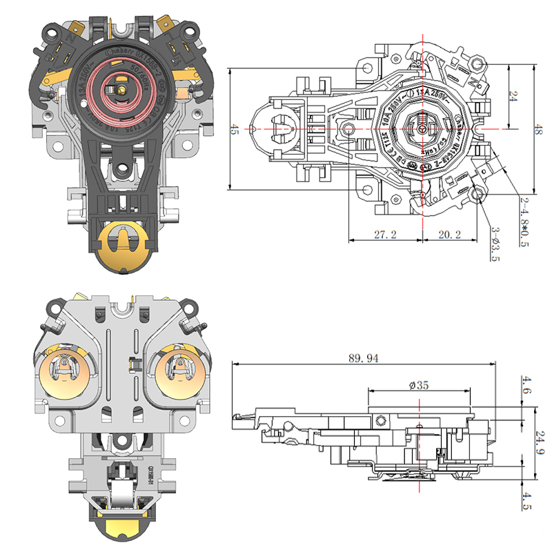
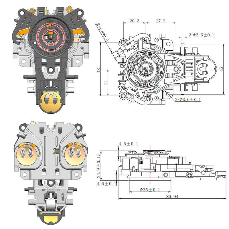
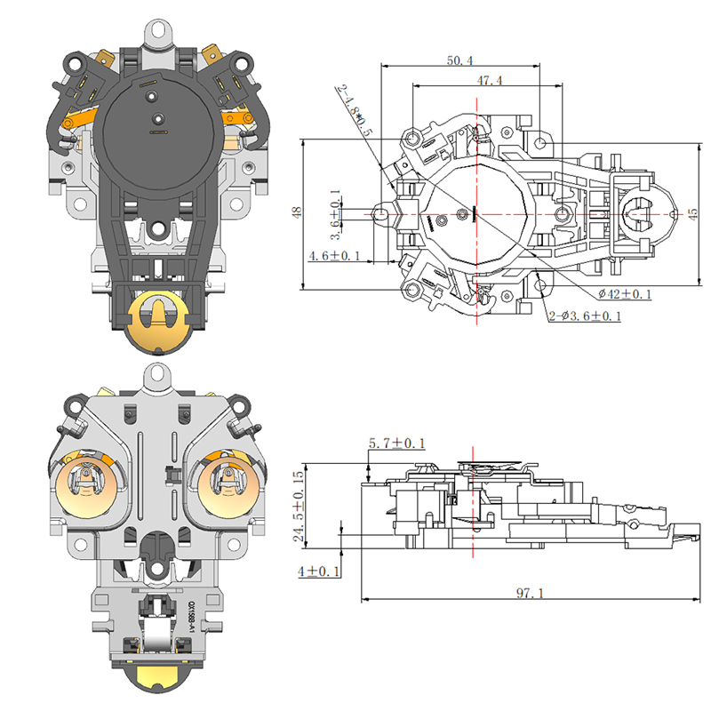
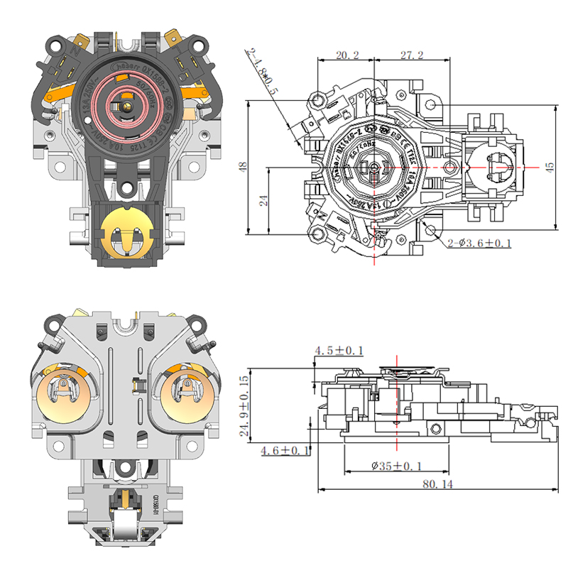
A Thermostat Coupler is a connector system with two halves. One half lives in the kettle bottom. The other half lives in the power base. When someone places the kettle onto its base, the two halves join. Electrical contacts meet. A separate signal path also connects. That signal path carries temperature information from the kettle to the control system.
Why the Coupler Is a Safety-Critical Component
A standard power connector only carries electricity. A Thermostat Coupler does that and more. It provides a pathway for temperature sensing signals. Those signals tell the base when the water has reached boiling point. The base then cuts power. No signal means no shut off. The coupler must work reliably every time.
Safety certification standards for electric kettles require this type of protection system. A kettle that cannot sense temperature and shut off automatically would not receive approval for sale. The coupler is not an optional feature. It is a required safety component.
How It Interacts With Heating Elements
The heating element sits inside the kettle bottom. It receives power through the coupler. A temperature sensor, often a bimetallic strip or thermistor, sits close to the element. This sensor monitors heat. Once the water boils, steam travels through a duct to the sensor. The sensor changes shape or resistance. That change sends a signal back through the coupler. The base receives the signal and opens a relay. Power stops.
The interaction happens in a fraction of a second. The user sees the kettle turn off. Behind that simple action, the coupler has transmitted power to the element and a shut off signal back to the base. Two different electrical functions through one connector.
How the Thermostat Coupler Prevents Overheating
Overheating happens when a kettle continues heating after the water has boiled. Without a working coupler, the heating element stays on. Water turns to steam. Steam leaves the kettle. Soon no water remains. The element then heats air instead of water. Air does not carry heat away efficiently. The element temperature rises quickly.
How Heat Signals Are Translated Into Power Control
Inside a properly functioning kettle, a bimetallic strip sits in the steam path. When water boils, steam flows over this strip. The strip consists of two different metals bonded together. Each metal expands at a different rate when heated. The strip bends. That bending motion pushes against a switch contact. The contact opens. The electrical circuit breaks.
The coupler carries this open circuit signal from the kettle body to the base. The base contains a relay that follows the state of that circuit. When the circuit opens, the relay opens. Power stops flowing to the heating element. The whole sequence relies on the coupler maintaining a clean, low resistance connection for the signal path.
Why Stable Connection Ensures Accurate Temperature Response
A poor connection in the signal path creates problems. The base relay may not receive the open circuit signal. The relay stays closed. The element continues heating. Alternatively, a poor connection may cause intermittent signals. The relay opens and closes rapidly. The kettle cycles on and off without reason.
Contact resistance matters for the power path as well. High resistance at the power contacts generates heat. That extra heat warms the coupler housing. The housing may soften or discolor. Over time, the contacts degrade further. A stable connection keeps resistance low and temperature response accurate.
| Safety Condition | Coupler Response | System Outcome |
|---|---|---|
| Normal boiling | Signal path closes correctly | Kettle shuts off at proper time |
| Overheating detected | Signal path opens | Power stops, element cools |
| Dry boiling | Rapid temperature rise triggers sensor | Shut off occurs before damage |
| Worn coupler contacts | Intermittent or high resistance signal | Delayed or failed shut off |
| Broken signal path | No shut off command reaches base | Continuous heating, risk of fire |
Dry Boiling Prevention Mechanism
Dry boiling occurs when a kettle is turned on without water or with very little water. The heating element becomes hot very quickly. No water means no steam. The normal steam based shut off system may not activate in time because no steam reaches the sensor.
Why Dry Boiling Is More Dangerous Than Overheating
Overheating after boiling happens gradually. The element warms air slowly. Dry boiling heats the element much faster. Without water to absorb heat, the element temperature rises within seconds. The element can reach temperatures that soften solder joints, melt plastic parts, or ignite surrounding materials.
A good Thermostat Coupler system includes secondary protection for dry boiling conditions. Some kettles use a separate thermal fuse or a backup bimetallic switch mounted directly against the element. Others rely on the main thermostat to respond faster when no water is present. The coupler must transmit the shut off signal regardless of which sensor triggers first.
How the System Identifies Abnormal Heating Conditions
Temperature sensors respond to rate of temperature change, not just absolute temperature. A normal heating cycle warms water slowly. A dry boiling condition warms the element very quickly. The sensor detects this rapid rise. The shut off mechanism triggers at a lower absolute temperature than during normal boiling.
The coupler must carry this early warning signal without delay. Any resistance or noise in the signal path could mask the rapid temperature change. The base relay would stay closed. The element would continue heating until a secondary fuse blew or the kettle caught fire.
Coupler Working Principle in Electrical Kettle Systems
The working principle combines electrical power delivery with thermal signal transmission. Two separate circuits share one connector housing.
Step-by-Step Energy Control Process
First, the user places the kettle on the base. The coupler halves engage. Spring loaded contacts press together. A central alignment pin ensures correct orientation. Second, the user turns on the kettle. Power flows through the base, through the coupler power contacts, and into the heating element. Third, a temperature sensor monitors the heating process. Once water boils, steam reaches the bimetallic strip. The strip bends. Fourth, the bending strip pushes a switch. The switch opens the signal circuit. The change travels through the coupler signal contacts back to the base. Fifth, the base detects the open circuit. A relay opens. Power to the heating element stops. Sixth, the user lifts the kettle. The coupler halves separate. The signal circuit resets.
Each step depends on the coupler maintaining clean contacts and stable connections.
Role of Kettle Base Connector in Safety Performance
The base connector is the lower half of the coupler system. It sits inside the power base. It contains female contacts that receive the male pins from the kettle side.
How Base Stability Affects Safety Accuracy
A stable base holds the kettle securely. The kettle should not rock or tilt when placed on the base. Rocking motion moves the coupler contacts relative to each other. Contacts that move during operation can arc. Arcing burns the contact surfaces. Burned surfaces increase resistance. Increased resistance generates heat. Heat damages the housing.
The base connector also includes the alignment features. A central post or ring guides the kettle into correct position. If this alignment feature bends or breaks, the kettle may not seat fully. Power contacts may touch only partially. Partial contact creates high resistance and arcing. Signal contacts may not touch at all. No signal contact means no shut off capability.
Contact Wear and Its Safety Implications
Every time someone lifts the kettle, the coupler halves separate. Every placement brings them together again. This repeated action wears the contact surfaces. Contact plating wears through. Base metal becomes exposed. Exposed base metal oxidizes. Oxidation increases resistance.
A worn base connector may still pass power. The signal contacts may wear faster than power contacts because they are smaller. A kettle that heats normally but never shuts off likely has a worn or broken signal path.
Thermostat Connector vs Basic Electrical Connectors
A basic electrical connector has one job. It carries current from one wire to another. The connection either works or fails. A kettle Thermostat Connector has multiple jobs. It carries heating current. It carries temperature signals. It must survive high heat. It must resist steam exposure. It must function correctly many times.
Why Standard Connectors Cannot Prevent Overheating
A standard power connector has no provision for a signal path. Two wires in, two wires out. That design cannot support a separate temperature sensing circuit. Installing such a connector in a kettle would remove the shut off capability. The kettle would heat continuously until someone unplugged it.
Standard connectors also use ordinary plastic housings. Those plastics soften and deform at temperatures a kettle coupler must endure. A deformed housing allows contacts to shift out of alignment. Misaligned contacts create high resistance. High resistance creates more heat. The failure accelerates.
Design Differences That Matter
A kettle Thermostat Connector uses heat resistant materials. The housing maintains its shape at elevated temperatures. Contacts use plating that resists oxidation at high temperatures. Signal contacts are designed for low current, dry switching applications. Power contacts are sized to carry heavy heating current without overheating.
The alignment system is another difference. A standard connector relies on the user to align pins and sockets visually. A kettle coupler uses mechanical guides. The kettle seats itself correctly regardless of orientation. This self aligning feature prevents misconnection errors.
Common Causes of Overheating and Dry Boiling Failures
Failures do not happen without reason. Understanding the causes helps with diagnosis and prevention.
How Small Connector Issues Lead to System Failure
Contact oxidation starts small. A thin layer of oxide forms on the contact surface. Resistance increases slightly. The contact runs a little warmer. Warmth accelerates oxidation. The cycle continues. Eventually the resistance becomes high enough that the contact generates significant heat. The housing around that contact melts. The contact shifts. The signal path breaks. The kettle no longer shuts off.
Another common failure is mechanical wear. The spring tension that holds contacts together weakens over time. Weaker tension means higher resistance. Higher resistance means heat. The same downward spiral occurs.
Thermostat Malfunction
The coupler is not the only part that can fail. The bimetallic strip inside the kettle may lose its calibration. After many heating cycles, the metal may not bend as far as it once did. The switch may not open completely. The signal circuit may remain closed even when steam is present.
A failed thermostat cannot be repaired through the coupler. The coupler transmits whatever signal the thermostat provides. If the thermostat fails to open, the coupler faithfully carries the closed circuit signal. The base relay stays closed. The kettle continues heating.
Poor Base Alignment
A base that has been dropped or knocked out of shape may not hold the kettle level. The kettle tilts to one side. The coupler contacts only meet on one edge. Contact area is reduced. Resistance increases. Heat builds at the reduced contact point. The overheating may damage the coupler before the thermostat has a chance to shut off normal boiling.
Coupler Testing Methods in Manufacturing
Testing ensures that each coupler leaving a factory will perform its safety function. Several types of tests are used.
Thermal Response Testing
A thermal response test checks whether the coupler transmits temperature signals correctly. Engineers place a kettle with a test coupler onto a base. The kettle is heated. Sensors monitor the signal path. The time between boiling and shut off is measured. A coupler that causes delayed shut off fails the test.
This test also checks for false signals. A coupler that creates noise or intermittent connections may cause the base to shut off prematurely. Premature shut off annoys users but is not dangerous. The test rejects couplers that show unstable signal behavior.
Electrical Continuity Testing
Every contact in the coupler is checked for continuity. A machine probes each contact and measures resistance. Power contacts must have very low resistance. Signal contacts must also have low resistance. Any contact showing resistance above the allowed limit is rejected.
Continuity testing also checks for shorts between contacts. The power circuit must remain completely separate from the signal circuit. A short between these circuits could send dangerous voltage into the low voltage signal system.
Durability Cycle Testing
A machine inserts and removes the coupler many times. After each set of cycles, technicians measure contact resistance and inspect for visible wear. A coupler that maintains stable contact resistance passes. A coupler that shows increasing resistance or visible contact damage fails.
Durability testing also checks the housing. The plastic should not crack, warp, or shed debris after many cycles. Any housing damage indicates poor material choice or design.
Safety Cut-Off Verification
The final test verifies that the coupler works with a complete kettle system. A test kettle is run through heating cycles with a dry boiling condition simulated. The shut off must occur within a safe time. Any failure results in rejection of the entire batch.
| Test Type | What Is Measured | Failure Indication |
|---|---|---|
| Thermal response | Time from boiling to shut off | Delayed or no shut off |
| Continuity | Contact resistance | High resistance or open circuit |
| Durability | Resistance after many cycles | Increasing resistance or wear |
| Short circuit | Isolation between circuits | Power leakage to signal path |
| Cut-off verification | Shut off during dry boil | Failure to stop within safe time |
Materials and Structural Design of Thermostat Couplers
The materials chosen for a coupler determine how long it will last and how reliably it will perform.
Heat-Resistant Materials
The housing must withstand the heat rising from the kettle bottom. Common materials include thermoset plastics and high temperature thermoplastics. These materials do not melt or soften at temperatures found near a heating element. They also resist deformation under constant pressure from spring loaded contacts.
The contacts themselves are made from copper alloys. Brass and phosphor bronze are common choices. These metals conduct electricity well and maintain their spring properties at elevated temperatures. Pure copper would soften too quickly.
Conductive Contact Design
The shape of the contact affects how well it performs. A rounded contact wears more slowly than a flat or pointed one. The contact area should be large enough to carry the heating current without excessive resistance. The spring force must be high enough to maintain a gas tight connection but not so high that the plastic housing deforms.
Plating protects the base metal. Nickel plating resists oxidation. Tin plating provides low contact resistance. Some couplers use silver plating for high conductivity. The plating must be thick enough to withstand many cycles without wearing through.
Insulation Structure
The space between power contacts and signal contacts must be sufficient to prevent arcing or leakage. Creepage distance is the shortest path along the surface of the insulating material. Clearance distance is the shortest path through air. A well designed coupler maintains these distances even after years of thermal cycling.
Maintenance and Replacement of Base Coupler Systems
A coupler that fails does not always require replacing the entire kettle. The Base Coupler can often be replaced separately.
Identifying Faulty Couplers
Signs of a failing coupler include intermittent heating, the kettle not shutting off, visible burning or melting on the base contacts, and a loose fit between the kettle and base. Any of these signs warrants inspection.
The user should unplug the base before inspecting. Look at the contacts in the base and on the kettle bottom. Discoloration, pitting, or black marks indicate arcing damage. Melted plastic near the contacts indicates overheating.
Replacement Compatibility
A replacement coupler must match the original in size, contact arrangement, and electrical rating. Measuring the distance between contacts and the overall diameter helps identify the correct part. Using a coupler with different dimensions may prevent the kettle from seating correctly.
OEM components are generally recommended over generic replacements. A generic coupler may use inferior materials or have slightly different dimensions. The safety performance cannot be guaranteed.
Risks of Using Incorrect Connector Types
Installing a connector not designed for kettle use creates serious risks. The plastic may melt. The contacts may overheat. The signal path may be missing entirely. The kettle would lose its shut off capability. A repair that saves a small amount of money could create a large fire hazard.
System-Level Role of Thermostat Coupler in Kettle Safety
The coupler does not work alone. It is one part of a complete safety system.
Coordination Between Heating and Control
The heating element, temperature sensor, coupler, and base relay must work together. A delay in any part of this chain reduces safety margin. The coupler must transmit signals quickly. The relay must open quickly. The sensor must respond quickly. A weak link anywhere in the chain compromises the whole system.
Why Safety Depends on System Integration
A high quality coupler cannot compensate for a poor thermostat. A sensitive thermostat cannot compensate for a worn coupler. The system works at the level of its weakest component. Proper evaluation of kettle safety requires looking at the whole system, not just one part.
Misconceptions About Kettle Safety Components
Many people hold incorrect ideas about how kettle safety works.
The “It Is Just a Connector” Misconception
Some people believe any connector will work as long as it fits. This belief ignores the thermal and signal transmission requirements. A connector that passes power but fails to pass the shut off signal is worse than useless. It creates a false sense of security.
Misunderstanding Thermostat Function
Others assume the thermostat is located in the base. It is not. The thermostat or temperature sensor is in the kettle body. The coupler carries the signal from that sensor to the base. Without the coupler, the base has no way of knowing what is happening inside the kettle.
Ignoring Dry Boil Protection Logic
Some people think a kettle will never boil dry because they always add enough water. Mistakes happen. A child may turn on an empty kettle. A user may forget to add water. The protection system exists for these situations. Disabling or bypassing the coupler removes that protection.
Key Takeaways on Overheating and Dry Boiling Prevention
A Thermostat Coupler is a safety component that prevents electric kettles from overheating or boiling dry. It carries power to the heating element and returns temperature signals to the base. Without a functioning coupler, the base cannot know when to shut off. The coupler prevents overheating by transmitting the open circuit signal from a bimetallic switch. When water boils, steam bends the switch. The switch opens. The coupler carries that open circuit to the base. The base relay opens. Power stops. The coupler also prevents dry boiling. Rapid temperature rise during dry conditions triggers the shut off faster than normal boiling. The coupler must transmit this early warning without delay. Any resistance or noise in the signal path could mask the danger.
Material choice and contact design determine coupler reliability. Heat resistant housings, oxidation resistant platings, and robust contact geometries all contribute to long service life. Testing during manufacturing verifies that each coupler will perform its safety function. The coupler integrates the kettle body and base into one functional safety system. A poor coupler makes a safe kettle unsafe. A good coupler allows the kettle to perform reliably over many years. Electric kettle safety depends on hidden interface engineering. The Thermostat Coupler is the unseen link between heating and control. Every automatic shut off, every prevented dry boil, every safe use relies on this small component working correctly. For reliable Thermostat Coupler components and technical support, Wenzhou Qianxun Electrical Technology Co., Ltd. provides quality Kettle Connector solutions. Regular inspection and timely replacement of worn couplers prevent dangerous failures and extend appliance life.
Featured Products

-
No. 2892, Ningkang East Road, Tiancheng Industrial Zone, Yueqing City, Zhejiang Province
-
 Email: Una@chaserr.cc
 -
 Phone: +86-13075775533
- GET IN TOUCH

Electric Kettle Thermostat Coupler Manufacturer