English
  中文简体
中文简体  Español
How Does Base Coupler Design Affect Kettle Assembly
A Base Coupler might look like a minor part of an electric kettle, but its position ripples out to affect much more than just the connection itself. When workers assemble a kettle base, they need to fit electrical parts, temperature control components, supports, and connection points into a genuinely tight space, often with only a few centimeters to work with.
A coupler that's easy to position makes this whole process clearer for whoever's standing at the workstation. An awkward design, on the other hand, creates extra handling and inspection work that eats into every single assembly cycle over a shift.
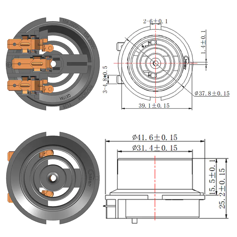
For manufacturers, assembly efficiency stays closely tied to component fit throughout. A Kettle Base Connector needs to match the surrounding structure and support the intended electrical arrangement without turning the assembly sequence into something unnecessarily fiddly. This becomes especially relevant once production settles into repeated assembly, routine inspection, and later component replacement down the line.
Why Does Base Coupler Design Matter in Electric Kettle Assembly?
Base Coupler design matters because the component sits within a larger assembly rather than working off on its own. Its shape, position, connection area, and relationship with nearby parts all affect how smoothly the kettle base actually comes together on the line.
An electric kettle base typically contains a heating connection, temperature control components, wiring, structural supports, and protective elements, all crammed into one compact housing. Each part needs enough room to do its job while staying accessible during production, and if the coupler doesn't fit naturally into that arrangement, workers end up repositioning it or nudging surrounding components out of the way just to make room.
A practical design makes the assembly sequence a lot easier to follow from station to station.
| Design Area | Effect on Assembly |
|---|---|
| Component shape | Helps identify the intended position |
| Connection layout | Supports easier fitting |
| Orientation | Reduces installation confusion |
| Support structure | Helps maintain component placement |
| Inspection access | Makes routine checking easier |
The goal here isn't simply making the coupler easy to install in isolation. It also needs to work naturally alongside the parts sitting right next to it. A small improvement in positioning can make a repeated assembly task noticeably more consistent without piling on any extra complexity.
This matters for both original production runs and replacement applications down the road. When a component is clearly designed for its intended kettle structure from the start, technicians spend a lot less time puzzling over how it's supposed to sit.
How Does Bimetallic Temperature Control Affect Component Arrangement?
Bimetallic temperature control shapes how components get arranged around the kettle base, since the temperature-sensitive mechanism needs to interact directly with the electrical control section nearby. A bimetal element changes shape as temperature shifts, and that physical movement gets used to operate an electrical switch, much like the strip inside an old-fashioned home thermostat.
This is the basic idea behind the Bimetal Thermostat Working Principle. The bimetal element responds to heat and moves in a controlled, predictable way, letting the switching mechanism flip the electrical state once the intended temperature condition gets reached.
In an electric kettle, the thermostat needs to work hand in hand with the heating and electrical connection system sitting around it. Its position has to correspond with the physical structure of the base, and a coupler located nearby shouldn't interfere with that delicate arrangement.
The Bimetal Thermostat Function ties to temperature sensing and switching rather than just providing a plain physical connection. This distinction matters during component selection, since a connector or coupler should support the thermostat assembly rather than get mistaken as a stand-in for the temperature-control component itself.
Designers can weigh several practical questions here:
- Where should the temperature-sensitive part be positioned?
- Can the switching section be assembled without obstruction?
- Is the connection area easy to access?
- Can workers identify the intended component orientation?
- Can the completed assembly be inspected conveniently?
These questions tie temperature control directly to assembly planning. A well-arranged base lets each component do its intended job while keeping the whole production process something a new worker can actually follow.
What Should Manufacturers Consider When Selecting a Coupler?
Manufacturers should focus on compatibility rather than judging a coupler purely by appearance. Two parts can look nearly identical sitting side by side in a bin, yet carry different connection arrangements, positioning requirements, or relationships with the surrounding components.
The Electric Kettle Base Coupler needs to correspond with the intended kettle base structure it's going into. Its physical form has to work with the assembly, while its connection method needs to suit whatever electrical layout was designed for that specific product.
Material choice matters here too, and not just as an afterthought. The component operates inside an appliance environment where heat, repeated use, and electrical connections all show up together, so the selected material and construction genuinely need to fit that reality rather than just looking sturdy on paper.
| Selection Consideration | Practical Question |
|---|---|
| Physical fit | Does it match the intended base structure? |
| Connection | Can it be installed without unnecessary adjustment? |
| Handling | Is it easy to position during assembly? |
| Surrounding parts | Does it allow related components to fit naturally? |
| Inspection | Can the finished connection be checked? |
| Replacement | Is the component clearly identified for future service? |
This approach helps buyers avoid picking a component just because the name or the appearance seems roughly right at a glance. Product compatibility should get confirmed through actual drawings, samples, product information, or a direct conversation with the supplier.
For component suppliers, clear product identification cuts down on misunderstandings too. A buyer should be able to tell exactly where the part gets used and how it relates to the kettle base well before production starts rolling.
How Can the Coupler Support a Clear Electrical Design?
A coupler forms part of a physical connection system, but its placement also shapes how the whole electrical arrangement gets organized. The power path, temperature control section, and heating components all need to work together within the base structure available to them.
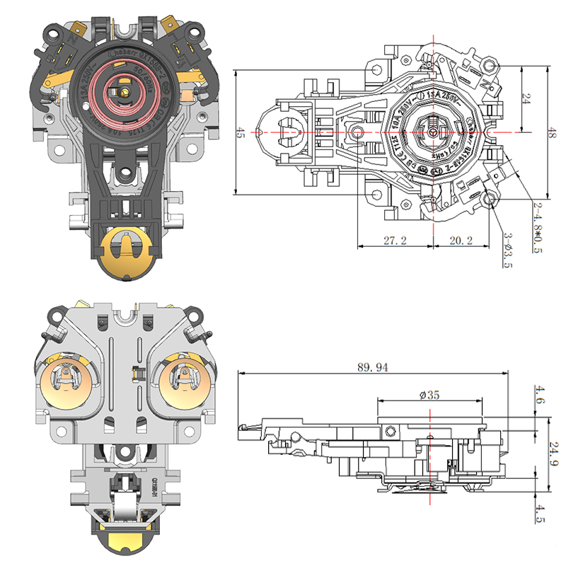
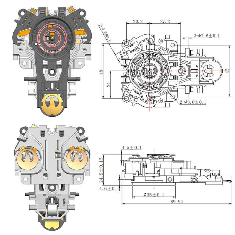
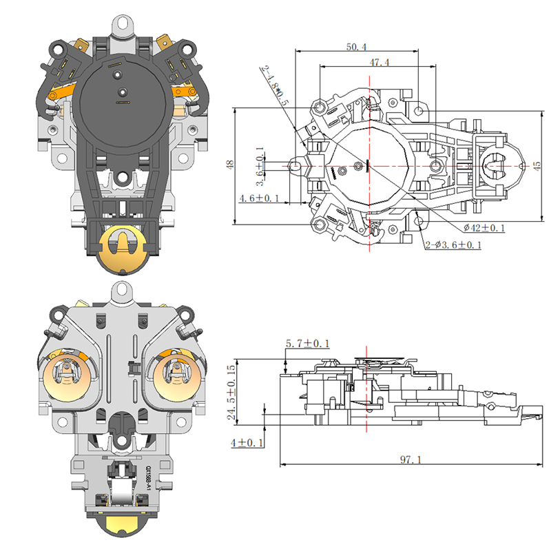
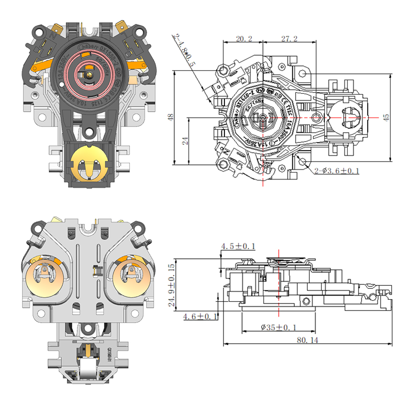
A Thermostat Coupler often sits near the temperature-control area, while other connection components link the base with the kettle body itself. Their positions should get planned together as part of the overall electrical layout rather than chosen one at a time in isolation.
A simple way to picture the arrangement:
The exact structure varies between kettle designs, sure. The basic requirement stays consistent regardless: related components need compatible positions so the intended electrical relationship can actually get established during assembly, not just hoped for afterward.
The Thermostat Connector can therefore get considered from both an electrical angle and an assembly angle at once. It should fit the intended connection while staying practical for workers to handle and inspect without a fight.
Good layout planning also helps avoid components crossing paths or interfering with each other unnecessarily. When the connection path stays clear and logical, assembly instructions become a lot easier to communicate, and workers get a more obvious sequence to follow step by step.
Can Better Component Fit Reduce Assembly Adjustments?
Better component fit reduces repeated adjustments because workers get a clearer sense of exactly where each part belongs. When a component doesn't align naturally with the surrounding structure, even a simple assembly task starts running slower and less consistently than it should.
Picture a production station where the same base component gets assembled over and over throughout a shift. If the worker has to rotate the coupler two or three times before finding the correct position, that extra fumbling becomes baked into every single cycle. A structure that makes orientation obvious removes a lot of that uncertainty right away.
| Assembly Difficulty | Possible Design Consideration |
|---|---|
| Unclear orientation | Use a recognizable component structure |
| Difficult positioning | Match the surrounding base layout |
| Limited working space | Plan the component sequence earlier |
| Repeated adjustment | Improve the relationship between connected parts |
| Difficult inspection | Keep important connection areas accessible |
This doesn't mean the coupler should get designed around assembly speed as the only priority. It still needs to satisfy the appliance's actual functional requirements and stay compatible with the temperature-control and electrical systems around it.
The practical aim comes down to a balanced design overall. Workers should be able to position the part without wrestling with it, while the finished assembly stays stable and easy to inspect afterward.
How Does Inspection Influence Coupler Design?
Inspection gets a lot easier when the component offers clear positioning references and accessible connection areas. A worker should be able to check whether the coupler installed correctly without having to disturb the parts sitting right next to it.
Coupler Testing can involve different checks depending on the specific product and production process in play. Physical fit, connection condition, positioning, and interaction with related components can all form part of a sensible inspection routine.
A simple inspection sequence might include:
- Check the component for visible damage.
- Confirm the intended orientation.
- Examine the connection area.
- Fit the related components.
- Check the assembled position.
- Record recurring fitting concerns.
The point of these checks isn't to pile more complication onto the production floor. Clear inspection points help catch problems before the kettle base moves along to the next production stage, saving a much bigger headache later.
A Bimetal Thermostat Diagram can also help explain the relationship between the temperature-sensitive element and the switching section when communicating the product's structure to a new team member. It proves a lot more useful when the visual information actually matches the real component arrangement and comes paired with practical assembly notes.
For replacement markets, inspection carries just as much weight. A replacement Kettle Connector should get checked against the intended assembly directly, rather than getting picked just because it looks similar to whatever part it's replacing.
How Does Assembly Sequence Influence Production Efficiency?
Assembly sequence shapes efficiency because the same component can be easy to install at one stage and genuinely hard to reach at another. If surrounding parts go in too early, the coupler can end up harder to position or inspect once everything else is already locked into place.
Manufacturers can factor the coupler into process planning from the start rather than bolting it on as an afterthought. A simplified workflow might involve preparing the base, positioning the connection component, fitting the temperature-control section, checking the electrical arrangement, and then completing the surrounding assembly around it.
The exact order shifts depending on the product design in question. What actually matters is that the sequence gives workers reasonable access to whatever they need to handle at each step along the way.
A clear process also helps a lot when several workers are involved across different stations. Each person can understand which parts should already be sitting in place and which components need to stay accessible for whoever's handling the next step.
The same principle applies when an Adjustable Bimetal Thermostat Switch is part of a particular appliance design. If adjustment or repositioning is required at some point, the surrounding coupler and connector arrangement needs to leave enough practical room for that operation to actually happen.
Good assembly planning ties closely back to component design as a result. A coupler that looks perfectly fine on a drawing can still cause real trouble if nobody thought through its actual installation stage on the floor.
Which Coupler Features Matter for Long-Term Production and Service?
For manufacturers and B2B buyers, a coupler deserves consideration throughout its working life, rather than only during installation. Production teams need a part they can handle consistently shift after shift, while service teams later need to identify, inspect, or replace that same component out in the field.
The Kettle Base Connector should carry a clear application and a recognizable structure from the start. This makes it a lot easier for purchasing teams to communicate with suppliers and for service personnel to identify the right replacement without guesswork.
Supplier communication plays an important role here too. Product drawings, samples, assembly information, and compatibility descriptions all help buyers understand exactly how a component fits into a particular kettle structure before committing to an order.
| Production or Service Need | Useful Design Focus |
|---|---|
| Repeated assembly | Consistent component positioning |
| Worker handling | Clear orientation |
| Quality inspection | Accessible connection areas |
| Product maintenance | Recognizable component structure |
| Replacement sourcing | Clear application information |
| Supplier communication | Accurate product identification |
The Coupler Function should therefore get weighed alongside its physical construction and actual application together, not treated as two separate boxes to check. A component can technically perform its connection role fine and still create avoidable work if it's genuinely difficult to handle or identify on the floor.
For electric kettle manufacturers, taking this wider view makes component selection a lot more practical day to day. The relationship between the coupler, thermostat, connector, and base structure becomes part of the production design itself, rather than sitting off to the side as some isolated purchasing decision made without the bigger picture in mind.
Featured Products


-
No. 2892, Ningkang East Road, Tiancheng Industrial Zone, Yueqing City, Zhejiang Province
-
 Email: Una@chaserr.cc
 -
 Phone: +86-13075775533
- GET IN TOUCH

Electric Kettle Thermostat Coupler Manufacturer