English
  中文简体
中文简体  Español
 Which Thermostat Coupler Fits Your Kettle Design?
A kettle that cuts out too early, fails to reach temperature, or shows intermittent heating behavior almost always traces back to the connection point between the base and the body — not to the heating element, not to the control board, and not to the power supply. The Thermostat Coupler sits at this junction and handles more than simple power delivery. It carries electrical current, supports the temperature sensing circuit that triggers automatic shut-off, and determines whether the kettle behaves safely and consistently across thousands of use cycles. Choosing the wrong component at this point — or sourcing one without understanding how its specifications align with the product's requirements — creates problems that surface in the field rather than in the factory. For manufacturers and procurement teams specifying this component, the selection decision deserves more structured attention than it usually receives.
What a Thermostat Coupler Is and Where It Sits
The Component That Connects Base to Body
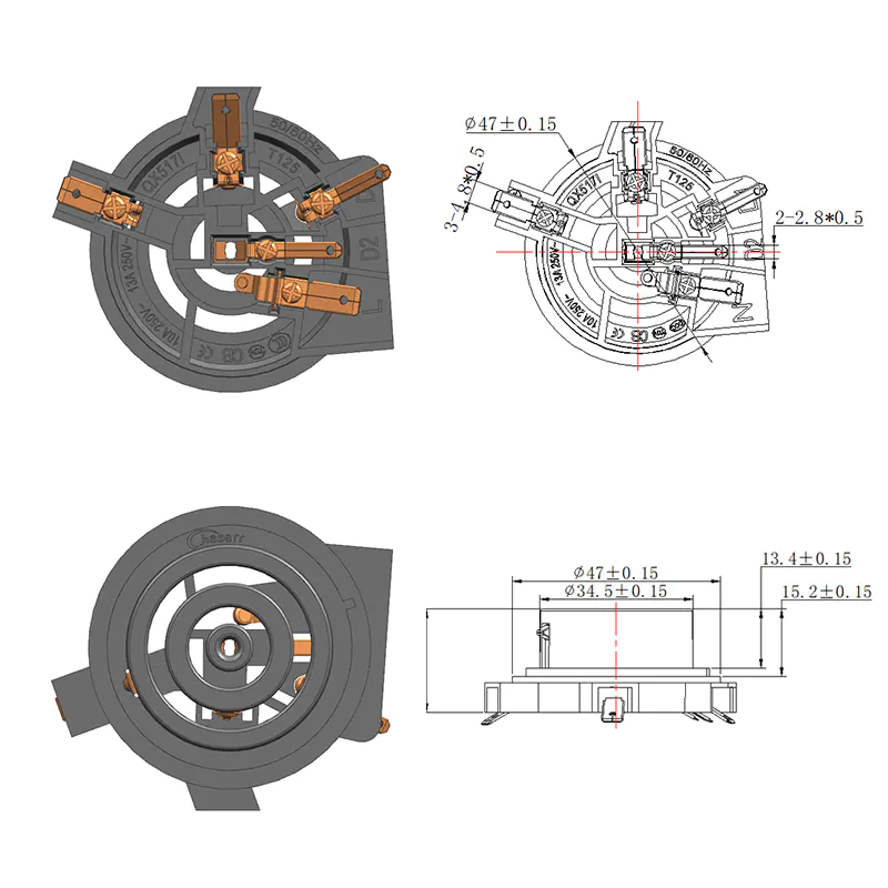
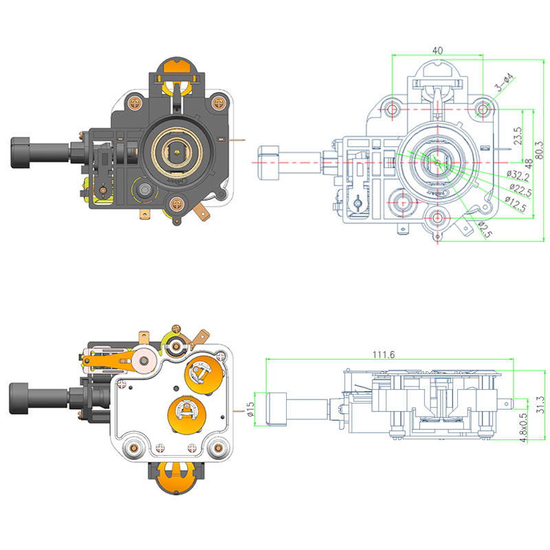
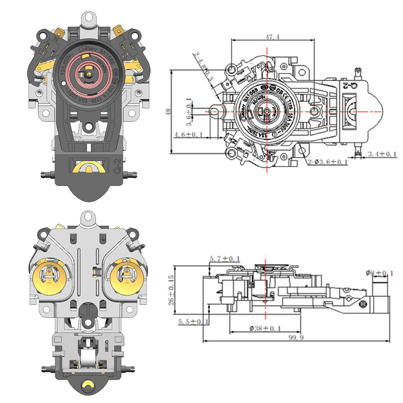
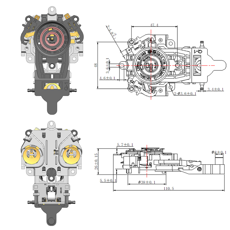
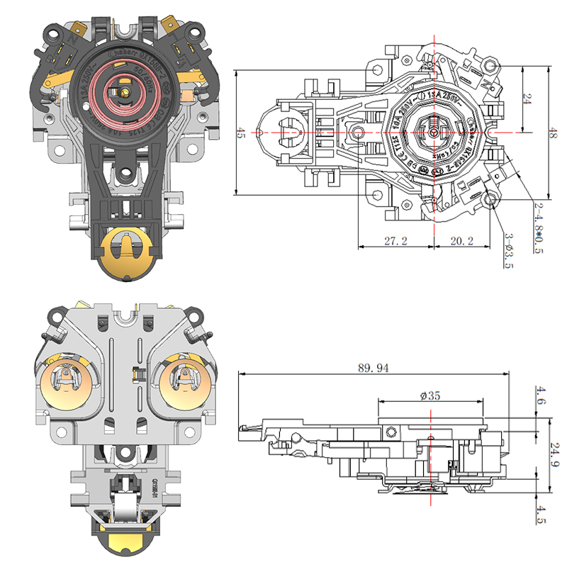
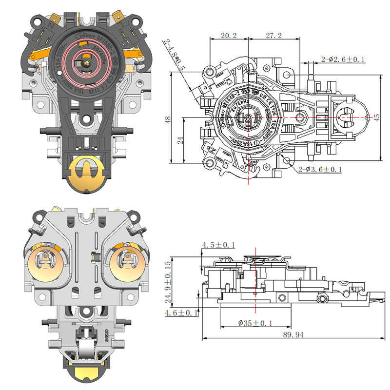
A Thermostat Coupler is the interface assembly that allows a kettle body to be lifted from and replaced onto its power base freely while maintaining consistent electrical contact. It typically consists of two mating components: a base unit mounted to the power platform and a body unit integrated into the kettle's underside. When the kettle is placed on the base, the two halves engage, completing the circuit and establishing the connection through which both power and control signals pass.
The design of this interface determines several things simultaneously:
- Whether current flows at the correct rating without resistance losses that generate heat
- Whether the temperature-control circuit maintains its signal path correctly
- Whether the automatic shut-off function receives the signal it needs to open the circuit when the water reaches the set temperature
- Whether the connection remains stable across repeated use cycles and varying placement angles
The component is not interchangeable across all kettle designs. Base geometry, current rating, connector direction, and control circuit type all vary between product platforms, and specifying a coupler without verifying these parameters against the intended application creates compatibility problems that are expensive to resolve after tooling and production have advanced.
What Does a Thermostat Coupler Actually Do
Four Functions Operating Simultaneously Through One Interface
The coupler's function is often described as "connecting the kettle to power," which is accurate but incomplete. The connection point handles several distinct operational requirements at the same time.
Power transmission: The coupler carries the full operating current from the power base to the heating element in the kettle body. The contact surfaces must be sized, finished, and made from materials that maintain low contact resistance under the current loads involved. High contact resistance at this point generates heat at the interface — heat that degrades the contact materials, reduces connection reliability, and in poorly specified products can damage the housing around the coupler over time.
Temperature control signal support: The Thermostat Coupler provides the physical path through which the temperature-sensing circuit in the kettle body communicates with the control components in the base. In designs where the automatic shut-off is triggered by a bimetallic actuator responding to steam, this path closes the circuit that opens the power relay. In designs with more sophisticated thermal sensing, the signal path carries a low-level electrical signal. Either way, the coupler must maintain this connection reliably even as the interface temperature rises during operation.
Automatic shut-off activation: When the water reaches boiling temperature, the thermostat mechanism in the kettle body initiates the shut-off sequence. The coupler provides the physical and electrical path through which this signal reaches the power-switching element in the base. A coupler with degraded contacts or misaligned housing may interrupt this path intermittently, producing the failure mode where the kettle continues heating beyond the set point — one of the more serious performance and safety concerns in this product category.
Safety protection during abnormal conditions: A correctly rated and properly functioning coupler plays a role in limiting the consequences of abnormal operating conditions — over-temperature events, dry boiling, or power supply anomalies. The contact ratings, material specifications, and housing design all contribute to how the component behaves when operating conditions deviate from the normal range.
How a Thermostat Connector Works Step by Step
The Sequence From Placement to Shut-Off
Understanding the operational sequence helps identify where specification gaps create problems and where quality variation matters most.
The kettle body is placed on the base. The two halves of the coupler align and engage. The engagement geometry — whether 360-degree or directional — determines how precisely the user must position the kettle.
Electrical contacts in the base half connect to corresponding contacts in the body half. The quality of this connection — contact area, surface finish, spring force — determines the resistance at the interface and therefore the heat generated during normal operation.
Power flows from the base through the coupler contacts into the heating element circuit in the kettle body. The current path must be continuous and stable throughout the heating cycle.
The thermostat circuit in the kettle body monitors temperature through a bimetallic element or thermal sensor positioned near the base of the kettle, where steam and heat accumulate as the water approaches boiling.
When the temperature threshold is reached, the thermostat mechanism activates — typically by a bimetallic disc that snaps or by a wax actuator that expands — sending a signal through the coupler to the power-switching element in the base.
The power relay or switch in the base opens, cutting current to the heating element. The kettle ceases heating. The coupler remains engaged but carries no current until the kettle is lifted and replaced.
The coupler is active during steps 2 through 5 of this sequence. Any degradation in its contact quality, alignment, or material condition affects the reliability of each stage.
Common Types of Kettle Base Connectors
Design Variants That Serve Different Product Platforms
Not all Kettle Base Connectors are identical in geometry or function. The product platform, target market, and design generation determine which type is appropriate.
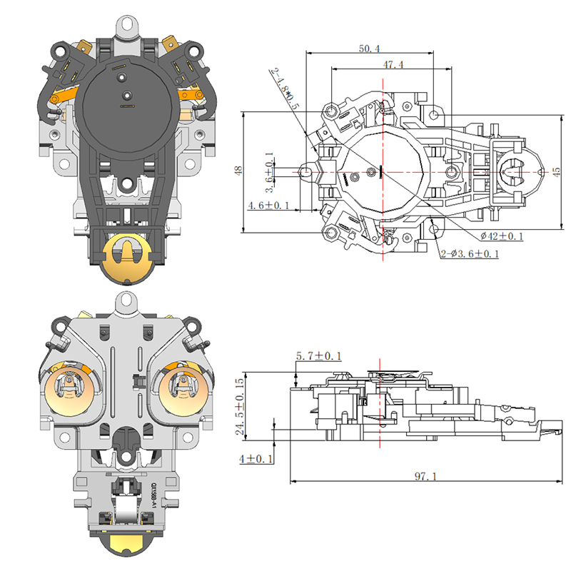
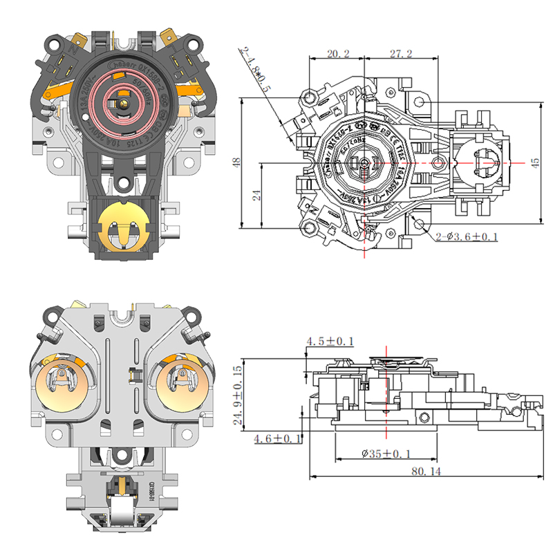
360-degree rotating connectors: The dominant format in contemporary kettle design. The base unit is circular and makes electrical contact regardless of which direction the kettle body is placed. This eliminates the orientation requirement that frustrated users of older directional designs. The 360-degree connector requires that all contacts be arranged concentrically, which constrains the number of independent circuits that can be accommodated but provides the placement flexibility that users expect from current products.
Fixed-direction connectors: Used in older product generations and some lower-cost designs. The kettle must be placed with a specific orientation to engage the contacts correctly. Simpler mechanically, but the user experience is less convenient. Still present in some regional markets and price tiers.
High-specification connectors for premium platforms: Some connector platforms incorporate additional features — improved contact materials, higher cycle ratings, enhanced sealing, or multi-pole designs that support additional control signals. These are used in products where durability, performance consistency, or advanced control features are priorities.
Custom OEM connector designs: Manufacturers with proprietary kettle platforms sometimes develop custom coupler configurations matched to their specific base geometry, control architecture, and certification requirements. These require tooling investment but provide competitive differentiation and supply chain control.
Key Factors When Choosing a Thermostat Coupler
What the Specification Actually Needs to Cover
The selection decision is not simply about matching a physical form factor. Several technical parameters determine whether the coupler will perform reliably in service and meet the certification requirements of target markets.
Current rating: The coupler must be rated for the current the kettle will draw during normal operation. Under-rated contacts generate excess heat and degrade faster. The current rating must include an appropriate margin above the operating current to account for contact resistance variation and aging.
Voltage compatibility: Kettle products are sold across markets with different supply voltages. A coupler must be specified for the voltage range of the target market. Some coupler designs are compatible across a range of voltages; others are not, and mixing specifications creates safety issues.
Contact material: The material of the contact surfaces — brass, copper alloy, silver-plated contacts, or other specifications — directly affects contact resistance, heat generation, durability, and corrosion resistance. Better contact materials reduce resistance losses, generate less heat at the interface, and maintain their performance over more use cycles. The material specification should be verified from the supplier rather than assumed from the product category.
Temperature resistance of housing and insulation: The coupler housing is located immediately adjacent to the heating element and is exposed to significant thermal loads during each use cycle. The housing material must maintain its dimensional stability and insulating properties across the full operating temperature range of the product.
Cycle life: The coupler engages and disengages every time the kettle is lifted and replaced. A household kettle used several times per day may accumulate thousands of engagement cycles per year. The coupler's rated cycle life must be appropriate for the expected product service life, with appropriate safety margin.
Certification requirements by market: Different markets require different safety certifications for electrical appliances including kettle components. Target market certification requirements must be confirmed before component sourcing, because the testing and approval process is specific to the component design and cannot be easily transferred to an alternative supplier.
Thermostat Coupler vs Standard Kettle Connector
| Performance Dimension | Thermostat Coupler | Standard Connector |
|---|---|---|
| Temperature control signal path | Integrated — supports thermostat circuit | Absent — power only |
| Automatic shut-off support | Yes — part of the control circuit | Limited or absent |
| Safety protection level | Higher — supports multiple protection functions | Basic |
| Contact material specification | Typically higher-grade | Variable |
| Certification requirements | More extensive | Simpler |
| Application range | Full-featured kettle designs | Basic or entry-level products |
| Cost | Higher | Lower |
| Complexity of integration | Requires matched thermostat system design | Simpler electrical integration |
The distinction matters for product planning. A design that specifies a standard connector and expects it to support temperature control functions will encounter problems in development — the component does not have the additional contact architecture required. Equally, specifying a Thermostat Coupler for a product that uses an alternative control topology adds cost without benefit. The component type must match the control architecture of the product.
How to Test a Thermostat Coupler
Verification Methods That Reveal Real-World Performance
Visual inspection of a coupler tells a limited amount. The performance characteristics that matter — contact resistance, thermal stability, cycle durability — require testing that goes beyond appearance.
Visual and dimensional inspection: Confirm that contact surfaces are clean, undamaged, and correctly positioned. Check housing for cracks, deformation, or material degradation. Verify that the engagement mechanism operates smoothly with correct spring force. These checks identify obvious defects but do not reveal electrical performance.
Continuity and contact resistance testing: Measure the resistance across each contact pair under the rated engagement force. Elevated resistance indicates poor contact surface condition, inadequate spring force, or incorrect contact geometry. This test identifies couplers that will generate excess heat in service before they are installed.
High-temperature performance testing: Subject the coupler to its rated operating temperature for a defined period and measure contact resistance before and after. A coupler whose contact resistance increases significantly after thermal exposure has materials or design features that will degrade in normal service.
Cycle life testing: Operate the coupler through a defined number of engagement cycles at rated current and verify that contact resistance and mechanical function remain within specification at the end of the test. This is the only method that validates the coupler's durability claim. Suppliers who cannot provide cycle life test data are representing a specification claim without supporting evidence.
Insulation and dielectric testing: Verify that the insulation between current-carrying contacts and the housing meets the requirements for the target market certifications. This is particularly important for products sold in markets with stringent appliance safety standards.
Common Problems and Their Root Causes
What Failure Modes Reveal About Component Quality
Understanding the failure modes that appear in field returns or production testing identifies where specification or sourcing decisions created risk.
Intermittent heating: Usually indicates contact resistance variation — either from a contact surface that degrades progressively or from engagement geometry that does not maintain consistent contact force across all placement angles. A 360-degree connector that makes reliable contact only in certain orientations has an alignment or spring-force problem in its design or manufacture.
Connector overheating: Indicates that the contact resistance is higher than the design assumption, generating heat at the interface. Root causes include contact material degradation, inadequate contact area, or operating the coupler above its current rating. Overheating accelerates further degradation and can damage the housing and adjacent components.
Auto shut-off failure: Suggests that the signal path through the coupler for the thermostat circuit is interrupted or degraded. The control signal contacts in the coupler may be corroded, misaligned, or mechanically damaged. This failure mode is particularly serious from a safety standpoint because it removes the protection that prevents the kettle from overheating.
Physical degradation of the housing: Discoloration, deformation, or cracking of the housing material around the coupler indicates that the thermal load of normal operation exceeds the material's capability. This is a material specification problem rather than a manufacturing defect, and it recurs regardless of which individual component is replaced.
How Manufacturers Evaluate and Source Electric Kettle Base Couplers
The Procurement Decisions That Affect Long-Term Product Performance
For manufacturers developing new kettle products or reviewing existing supply arrangements, the coupler selection decision involves more variables than a simple component purchase.
Key evaluation points when assessing suppliers:
- Does the supplier provide independently verified test data for cycle life, contact resistance, and thermal performance — or only stated specifications?
- What certification documentation is available for the target market requirements, and is it specific to this coupler design or carried over from a related product?
- Can the supplier accommodate custom configurations — modified contact arrangements, housing geometry adjustments, or specific material grades — for OEM applications?
- What is the supply chain's ability to maintain specification consistency across production batches? Contact material grades and plating specifications vary between batches in lower-rigor manufacturing environments, producing coupler-to-coupler variation that creates field reliability problems.
- What is the supplier's technical responsiveness during product development? Coupler integration problems often emerge during development testing, and resolving them requires the supplier to understand and respond to specific technical feedback.
These questions separate suppliers who can support a product through its development and production lifecycle from those who can supply a catalog component but cannot support the engineering decisions that affect how well it performs.
Selecting a Coupler That Serves the Product and the Market
The Thermostat Coupler's position in the product — at the interface between power supply and kettle body, carrying both operating current and control signals — means that specification errors and sourcing compromises show up directly in product performance and reliability. Getting the selection right involves matching current rating, contact material, housing thermal resistance, cycle life, and certification requirements to the actual demands of the product and its intended market, rather than treating the component as a commodity. Wenzhou Qianxun Electrical Technology Co., Ltd. develops and manufactures Thermostat Couplers and Kettle Base Connectors for household electric kettle applications, covering a range of current ratings, connector configurations, and certification requirements across international markets. Their engineering team works with kettle manufacturers through the development and sourcing process — from component specification to integration testing — to ensure the coupler functions correctly within the specific control architecture and certification context of each product. For procurement teams and product engineers evaluating coupler sourcing for new or existing kettle platforms, reaching out to their technical team to discuss specifications, test data, and OEM options is a practical starting point.
Featured Products

-
No. 2892, Ningkang East Road, Tiancheng Industrial Zone, Yueqing City, Zhejiang Province
-
 Email: Una@chaserr.cc
 -
 Phone: +86-13075775533
- GET IN TOUCH

Electric Kettle Thermostat Coupler Manufacturer