English
 中文简体
 Español

Steam Kettle Switch Integration: Keep the Steam Path and Linkage Clear
A steam-operated kettle switch does not work in isolation from the appliance around it. The kettle must present the intended steam interface and mechanical operating arrangement to the selected component. For an appliance development team, this makes steam kettle switch integration a system-coordination task rather than a simple purchase based on a temperature marking.
Before approving a switch for production, bring the component supplier into the mechanical interface review. The aim is to identify the required steam path, mounting features and switch operating linkage for the actual kettle design. Any safety or electrical evaluation remains part of the complete appliance development process.
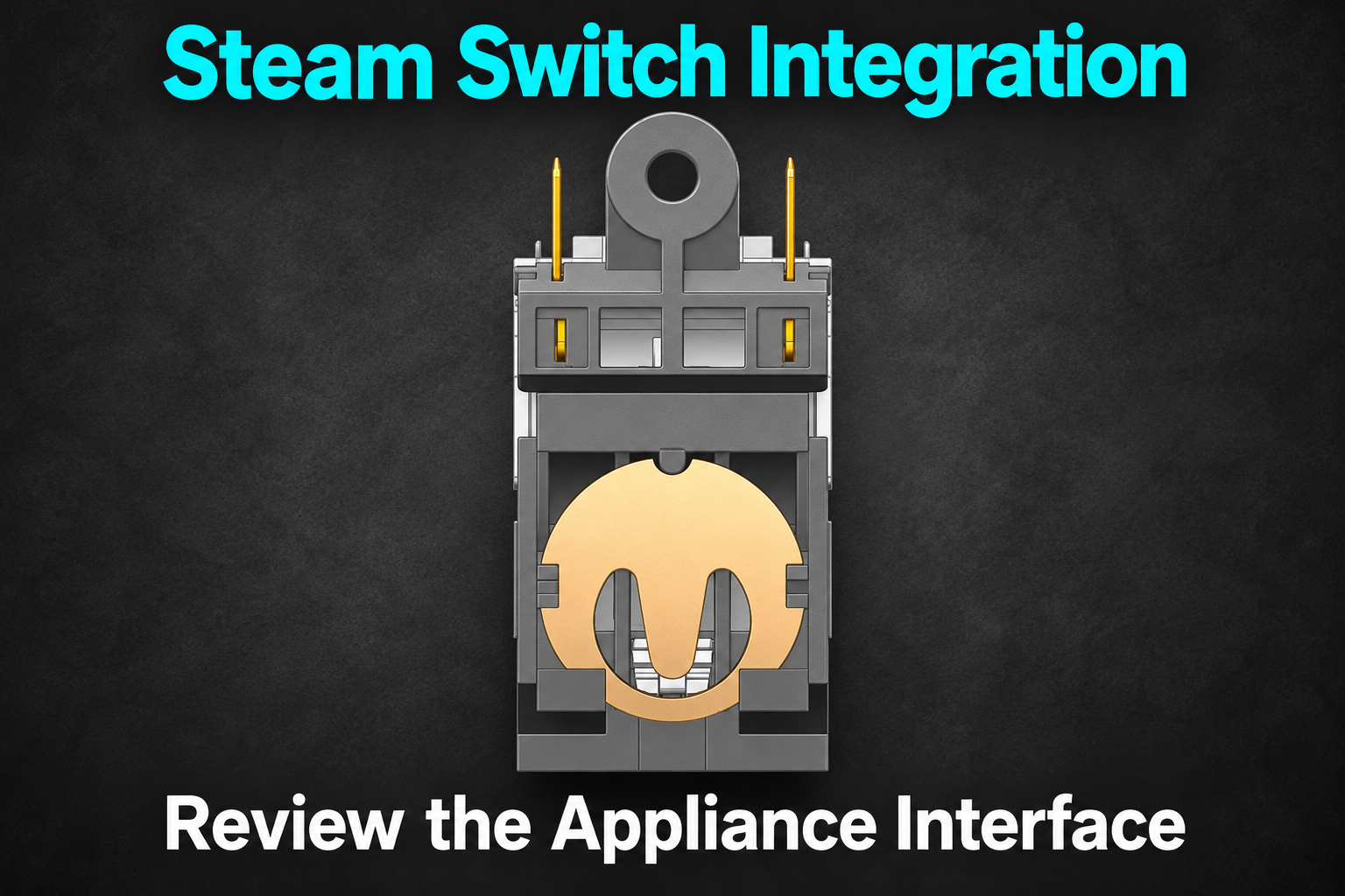
A switch is one part of the shutoff system
The Qianxun category for steam kettle thermostat switches describes components used in steam-responsive kettle shutoff arrangements. That establishes the product family, but it does not establish that every switch can be installed in the same housing or connected to the same steam channel.
Identify the exact model, drawing revision and offered configuration. Ask the supplier to distinguish the interfaces and functions relevant to that version. Avoid transferring a rating, feature or installation detail from another component that shares the category page.
Keep the complete kettle design in view. Steam delivery, switch mounting and the user's operating control interact through the appliance structure. A successful demonstration of a loose component cannot by itself prove the behaviour of the assembled kettle.
Trace the kettle steam path on the drawing
Show where steam is collected, how it reaches the specified switch interface and which surrounding parts form that route. Ask the supplier to confirm the required connection conditions for the chosen model. Do not guess a universal inlet size or channel geometry from a product photograph.
The review should make assembly dependencies visible. A lid feature, moulded passage or adjoining housing may form part of the intended steam route. If it is omitted from the review, the team may approve the switch while leaving the actual delivery path unresolved.
Identify which drawing controls each interface and which team owns a change. This is useful when the kettle body, handle and switch are developed by different suppliers. Each can appear correct in isolation while their assembled interfaces still need coordination.
Check the switch operating linkage without forcing it
Show how the external control moves the selected switch. Request the manufacturer's permitted travel, direction and any relevant interface limits. Do not assume that the visible lever can be driven from any angle or used as a structural stop.
Review the complete movement with the surrounding housing fitted. The operating control needs its intended motion, and the switch needs the approved connection to it. If the control reaches a housing stop before the required action is completed, that is an engineering issue to resolve, not something to correct by pressing harder.
| Appliance interface | Information needed | Review outcome |
|---|---|---|
| Steam connection | Supplier requirements and kettle passage drawing | A defined route to the intended interface |
| Mounting | Component drawing and support arrangement | A controlled installation position |
| Operating control | Linkage geometry and permitted movement | A compatible mechanical action |
| Nearby structure | Closed-housing assembly view | Space for the intended operation |
| Electrical connection | Approved terminal and harness information | A separate, documented wiring interface |
| Evaluation | Complete-appliance test plan | Defined evidence for the final design |
This table is an integration map. It deliberately avoids replacing the supplier's engineering data with generic values that may not apply to the selected switch.
Use the representative appliance for evaluation
Agree the sample configuration before conducting tests. Include the intended kettle body, handle, steam route, control and selected component version. Record any temporary part or prototype difference that could affect interpretation.
Have qualified personnel perform the applicable evaluation under an approved plan. Do not improvise live electrical or hot-steam tests for a purchasing demonstration. The plan should define operating conditions, observations, acceptance criteria and the people responsible for assessing them.
Separate findings from conclusions. For example, a recorded delay or failure to operate under a defined condition is a finding requiring investigation. It should not automatically be assigned to the switch without reviewing the steam interface, linkage, assembly and test setup.
Understand the limits of component documentation
A component drawing or approval document has a defined scope. Ask which information applies to the offered version and how it relates to the intended application. Do not describe a component certificate as proof that the finished kettle automatically complies with every requirement in the destination market.
Likewise, do not assume a steam-responsive function establishes every other protective function an appliance may need. The complete safety architecture must be reviewed by the responsible appliance engineering and conformity-assessment parties. Keep function descriptions precise in the purchasing specification.
If the design changes after the sample evaluation, review the affected evidence. A revised steam passage, control linkage or component mounting may need further assessment even if the commercial switch code has not changed. Let the technical team define that scope rather than treating all mechanical changes as cosmetic.
Release the complete interface, not a loose part
- Record the exact switch version and supplier requirements.
- Coordinate the steam route across all parts that form it.
- Check mounting and operating linkage in the closed assembly.
- Define the electrical connection separately from mechanical fit.
- Evaluate a representative appliance under the agreed plan.
- Control later changes to the interfaces used in that evaluation.
Send the coordinated interface drawings with the component enquiry. Steam kettle switch integration is clearer when the supplier can see the actual appliance arrangement and the buyer knows which questions belong to the component, which belong to the kettle structure and which require complete-appliance evidence.
Featured Products
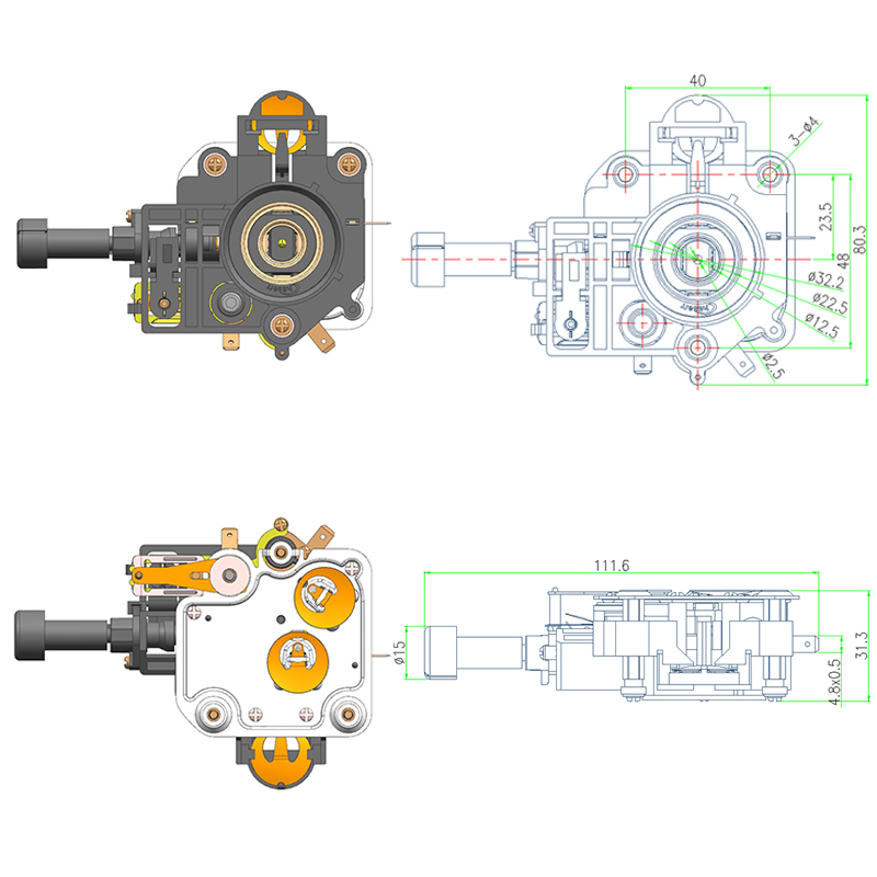

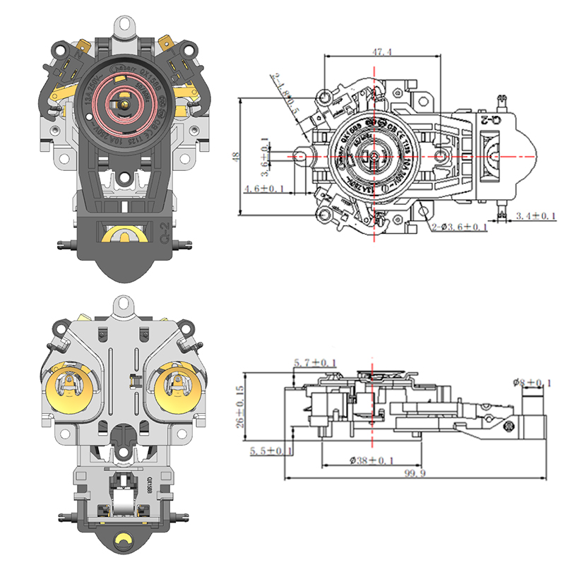
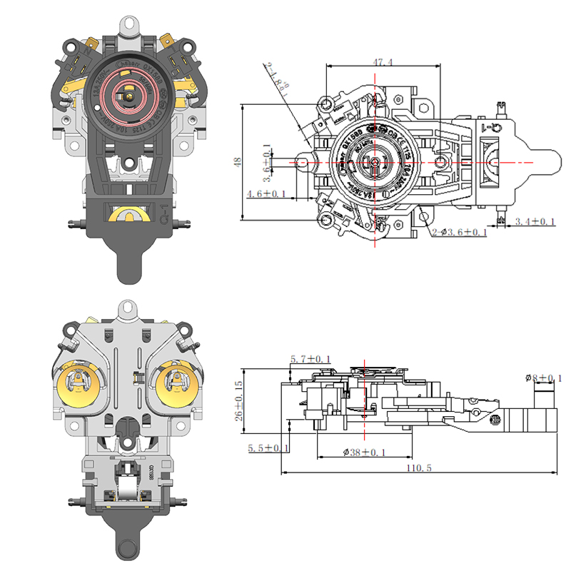

-
No. 2892, Ningkang East Road, Tiancheng Industrial Zone, Yueqing City, Zhejiang Province
-
 Email: Una@chaserr.cc
-
 Phone: +86-13075775533
- GET IN TOUCH

Electric Kettle Thermostat Coupler Manufacturer