English
 中文简体
 Español

Kettle Coupler Terminals: Check the Harness Connection Before Ordering
The component fits the mounting holes, but the harness connector cannot be inserted after the surrounding housing is assembled. This is the kind of interface problem a kettle manufacturer can uncover before production by reviewing the terminals and harness together. Kettle coupler terminals should be specified as connection features within an appliance assembly, not merely visible metal tabs on a product image.
The review belongs to the appliance's qualified engineering team and the component supplier. Its purpose is to agree the intended mating arrangement and assembly process. It is not a reason to force a connector onto a tab, bend a terminal for convenience or bypass the appliance's electrical evaluation.
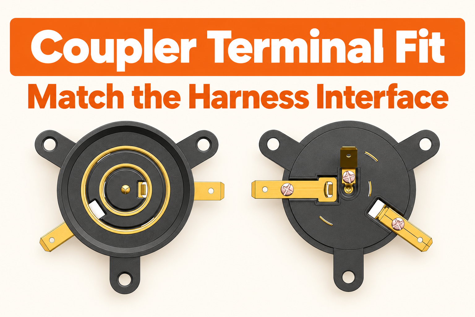
Freeze the two sides of the connection
Identify the exact coupler model and drawing revision, then identify the proposed harness connector. Share the controlled drawings or specifications for both. A coupler terminal drawing without the mating connector information leaves half the interface undefined.
When evaluating three-ring kettle couplers, select the specific offered configuration. Do not assume that every product in the category has the same tab dimensions, orientation or circuit assignment. The approved interface should remain tied to the model even if the surrounding plastic housings look similar.
Ask the supplier which terminal dimensions and tolerances control mating. Have the harness supplier confirm the connector specification intended for those dimensions. Compatibility should come from those documented interfaces, not a visual comparison with a connector already used on a different appliance.
Check orientation before checking convenience
Show how the coupler is installed and where the harness approaches it. The terminal may be accessible with the component loose on a bench but difficult to reach inside the final housing. Include the planned assembly sequence and the space required for the approved insertion method.
Confirm whether any terminal is supplied in a particular orientation and whether an alternative is available as a separately approved version. Do not instruct line operators to rotate or reshape a terminal to suit the harness. A needed geometry change should be referred to the suppliers and responsible designers.
Ask about retention or locking features in the specified mating connector. Define the approved way to confirm engagement. The answer should follow the actual connector design rather than assuming that an audible click or a particular insertion force is universal.
Review the connected harness inside the housing
Harness connector fit includes the connector body and the lead exit, not just the metal mating area. Show the space occupied after connection. Check the routing with the appliance closed according to its approved assembly instructions.
The engineering review should address nearby moving parts, hot regions, edges and any relevant insulation or separation requirements. Use the appliance design criteria and applicable evaluation process. Do not replace those requirements with a generic clearance number copied from another product.
| Interface item | Document to exchange | Question to resolve |
|---|---|---|
| Terminal geometry | Coupler drawing and revision | Which dimensions control the mating feature? |
| Connector | Harness part specification | Is the proposed contact intended for this interface? |
| Orientation | Installed assembly view | Can the connector approach correctly? |
| Lead exit | Harness routing drawing | Where does the wire sit after connection? |
| Retention | Approved assembly and inspection method | How is correct engagement verified? |
| Circuit identity | Controlled connection information | Does each lead reach the intended point? |
Keep physical fit and circuit identity as separate checks. A connector that seats does not establish that the wiring assignment is correct or that the appliance has passed its required electrical assessment.
Agree what the sample demonstration will establish
Use the actual proposed coupler and harness parts for the sample review. Record their references and revisions. Check the assembly sequence using the specified tooling and instructions, with qualified personnel responsible for any electrical work.
Define acceptance criteria before the evaluation. If the project requires measurements or tests beyond a fit demonstration, the responsible technical team should specify the method, equipment and conditions. Do not describe a simple manual insertion check as proof of long-term electrical performance.
Record difficulties accurately. A connector that needs unexpected force, cannot fully seat or interferes with the housing is an unresolved finding. Stop and seek the relevant technical review instead of adjusting the part informally until it appears to fit.
Make interface changes visible to both suppliers
The appliance maker may purchase the coupler and harness from separate sources. Give each supplier the same approved interface information. A change to one side should trigger a review of the other even when the commercial part name stays unchanged.
State which dimensions and features require approval before substitution. A proposed alternative terminal plating, contact geometry or harness connector should not be treated as an automatic equivalent. The responsible engineers need the actual change details to assess compatibility and any required re-evaluation.
For repeat orders, retain a reference assembly or clear identification record. Receiving staff can check identity against the order, while technical staff handle dimensional or functional questions under the agreed plan. Avoid asking warehouse personnel to decide electrical equivalence from a photograph.
Put the interface in the order file
- Identify coupler and harness references with current revisions.
- Exchange the controlling mating dimensions and connector specification.
- Show insertion direction and the connected lead route.
- Agree engagement checks and the scope of sample evaluation.
- Control substitutions on both sides of the connection.
- Retain the approved assembly information for repeat orders.
A clear review of kettle coupler terminals connects purchasing with the real assembly process. It gives both suppliers a defined interface and gives the appliance team a practical way to prevent a mounting-compatible part from becoming a harness-incompatible production problem.
Featured Products


-
No. 2892, Ningkang East Road, Tiancheng Industrial Zone, Yueqing City, Zhejiang Province
-
 Email: Una@chaserr.cc
-
 Phone: +86-13075775533
- GET IN TOUCH

Electric Kettle Thermostat Coupler Manufacturer