English
 中文简体
 Español

Kettle Coupler Seating: What Should the Mounting Review Include?
A coupler fits the opening in an appliance base, yet the assembled kettle does not sit as expected. The problem may lie outside the electrical component itself: the housing, locating surfaces or fixing arrangement may position it differently from the approved sample. For appliance manufacturers, kettle coupler seating should therefore be reviewed as an assembly interface.
This is not an invitation to alter a component until it fits. The useful purchasing task is to give the component supplier and appliance designer the same mounting information, then agree which combination is being evaluated. Electrical suitability and appliance safety require their own competent assessment; a successful mechanical fit does not establish either one.
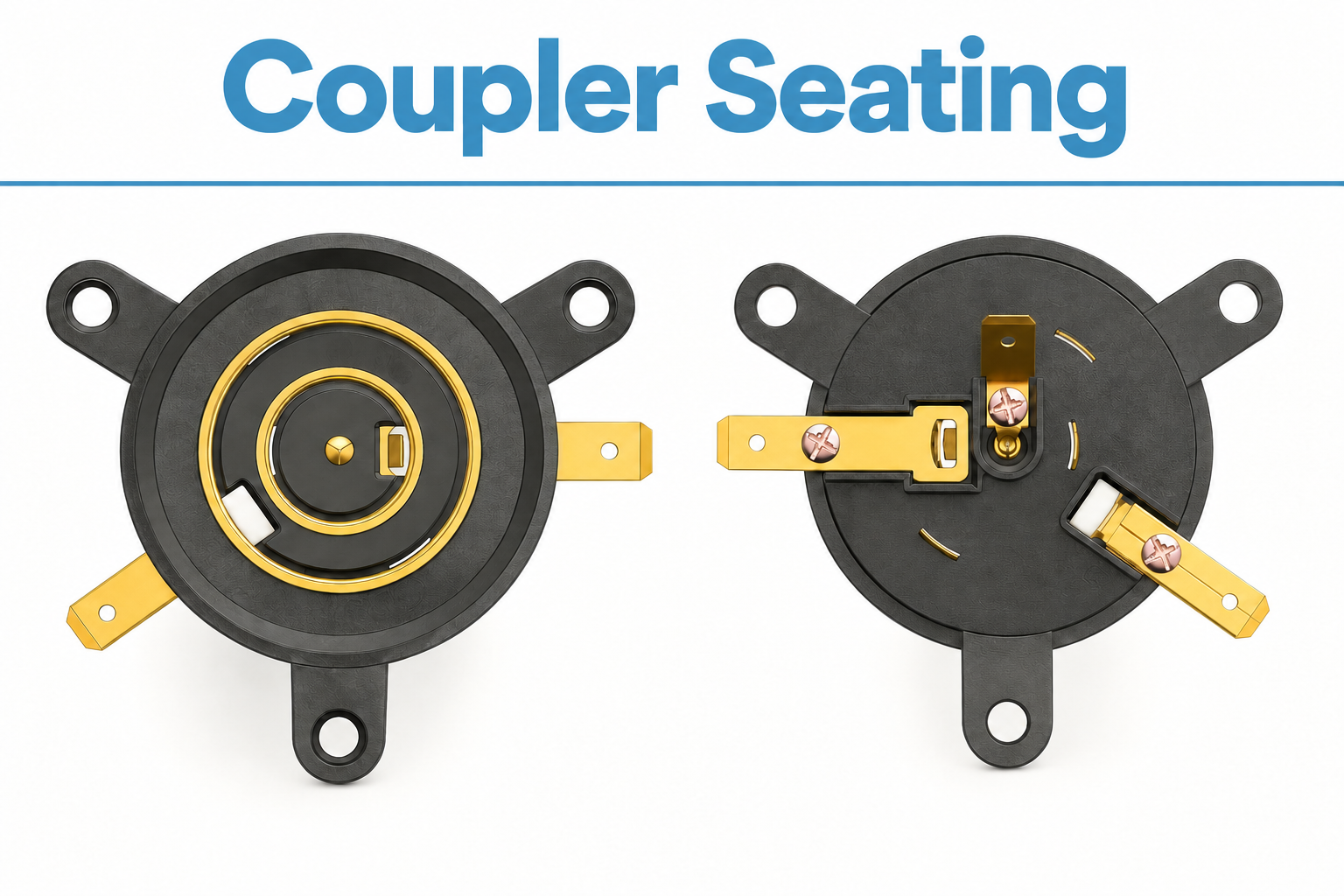
Review the mating assembly
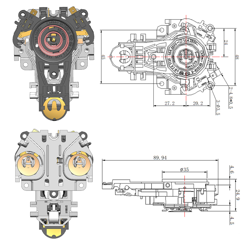
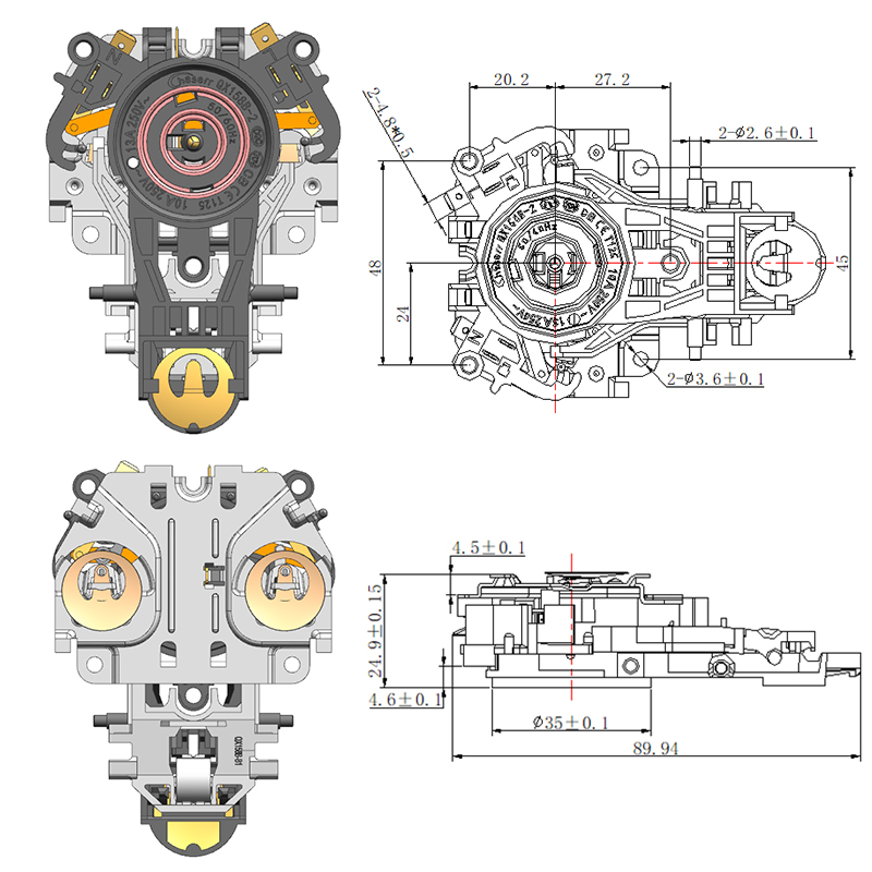
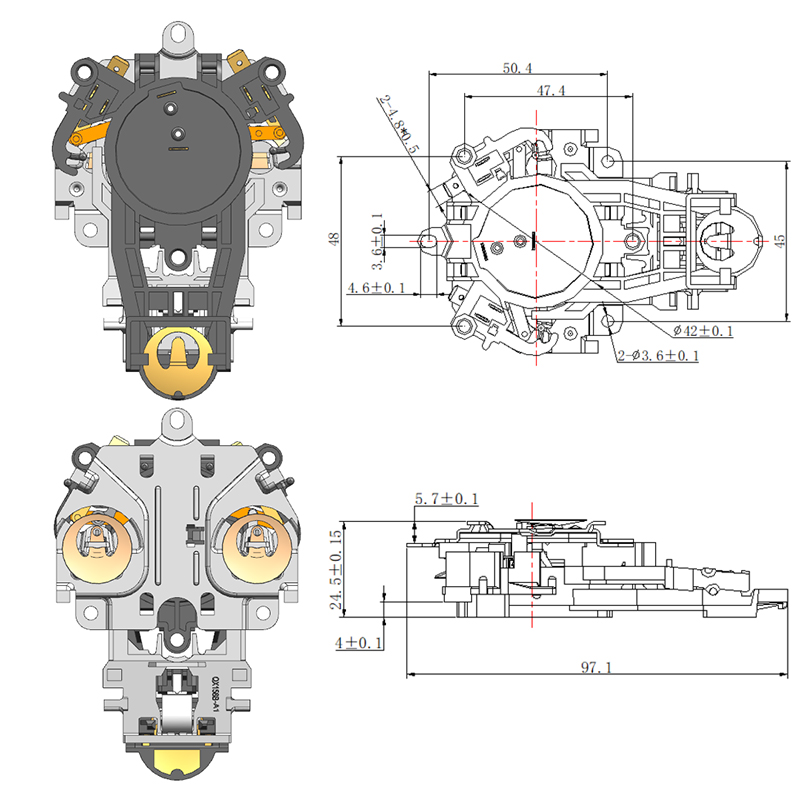
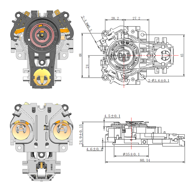
Use the automatic three-ring kettle coupler as a starting point for the model enquiry, then request the current controlled drawing for the exact version quoted. Product photographs and catalogue illustrations help identify the arrangement but should not replace the approved interface information.
Identify both mating components. A component on the kettle and a component in the base need to be reviewed as the intended pair. Do not assume that a similar appearance or ring arrangement makes parts from different versions interchangeable. Ask the supplier to identify the supported combination clearly on the quotation and sample record.
The appliance designer should supply the relevant housing section, locating features and fixing detail. Mark which surfaces establish the component position. A review that shows only the outer opening can miss a shoulder, rib or fastener boss that determines where the coupler actually sits after assembly.
Separate location from clamping
A locating feature establishes position; a fixing arrangement retains the part. Ask which feature performs each role in the proposed assembly. Do not rely on a screw to pull a poorly seated component into position unless the documented design specifically requires that assembly method.
Review the housing material and build-up at the interface. A mounting drawing needs the finished geometry that the component meets, including relevant ribs and support surfaces. If the appliance housing is still being developed, clearly identify provisional dimensions so a supplier's review is not mistaken for approval of an unfinished design.
| Interface item | Information to supply | Question to resolve |
|---|---|---|
| Locating surface | Housing section and component datum | What establishes the installed position? |
| Fixing points | Hole pattern and fastener detail | How is the part retained? |
| Mating pair | Both exact component references | Are these versions intended to work together? |
| Surrounding ribs | Complete local geometry | Could the housing interfere? |
| Assembly sequence | Order of fitting and access | Can the part seat before tightening? |
Examine the assembly sequence
A component can be compatible in the final drawing but difficult to position during production. Review how it enters the housing and when the mating parts, wiring and fasteners are installed. The sequence should leave access for the approved assembly method without forcing the terminals or component body.
Ask the assembly team to identify a repeatable way of recognizing correct seating before the next operation hides the interface. Depending on the design, that may involve a defined visual condition or an agreed fixture check. The method and acceptance criteria should come from the responsible engineering review rather than an improvised universal rule.
Keep torque or other assembly settings tied to the applicable supplier instructions and appliance design. An arbitrary setting borrowed from another product is not evidence of suitability. If the instructions are incomplete, obtain clarification while the sample is available and before the process is released to production.
Use a representative housing sample
A loose component demonstrates its own geometry, while a representative housing shows the combined interface. Use the intended component pair and production-representative local geometry to assess seating. Record any difference between the trial housing and the planned production version.
Do not hide a mismatch by trimming a rib or adding a spacer without engineering approval. Such a change can affect more than the visible fit. Record the observed interference, identify the responsible drawing and return the issue to the component supplier and appliance designer for coordinated resolution.
- Confirm both component references and the housing drawing revision.
- Fit the parts using the documented assembly sequence.
- Check the agreed seating condition before the interface is concealed.
- Record interference or unexpected movement without informal modification.
- Review the corrected assembly before approving production release.
Control changes to the surrounding plastic
A later housing change can invalidate an earlier fit review even when the coupler purchase code stays the same. Changes to support ribs, bosses, wall sections or locating features should trigger a check of the affected interface. The change request needs to identify what moved and which sample or drawing established the previous approval.
The same discipline applies when a second tool or alternate housing supplier is introduced. A part described as equivalent should be compared against the relevant controlled features. A photograph of the outer appliance does not prove that hidden mounting details are unchanged.
Retain a small assembly record linking the coupler version, mating component, housing revision and approved process. This helps purchasing distinguish a repeat order from a request that needs a fresh review. It also gives production a defined reference when an assembly does not sit as expected.
Release the interface with its limits understood
The final decision should state what has been checked and what remains subject to electrical, functional or appliance-level evaluation. Mechanical seating is one part of the product review and should be reported in those terms. It should not be presented as a complete safety approval.
A clear mounting review makes the supplier discussion more productive: the team can compare the actual locating surfaces, mating pair and assembly sequence instead of debating whether a component looks close enough. Resolve those details before the appliance layout and production process become difficult to change.
Featured Products
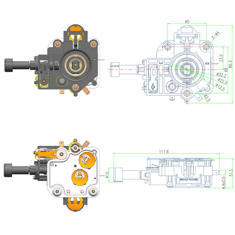

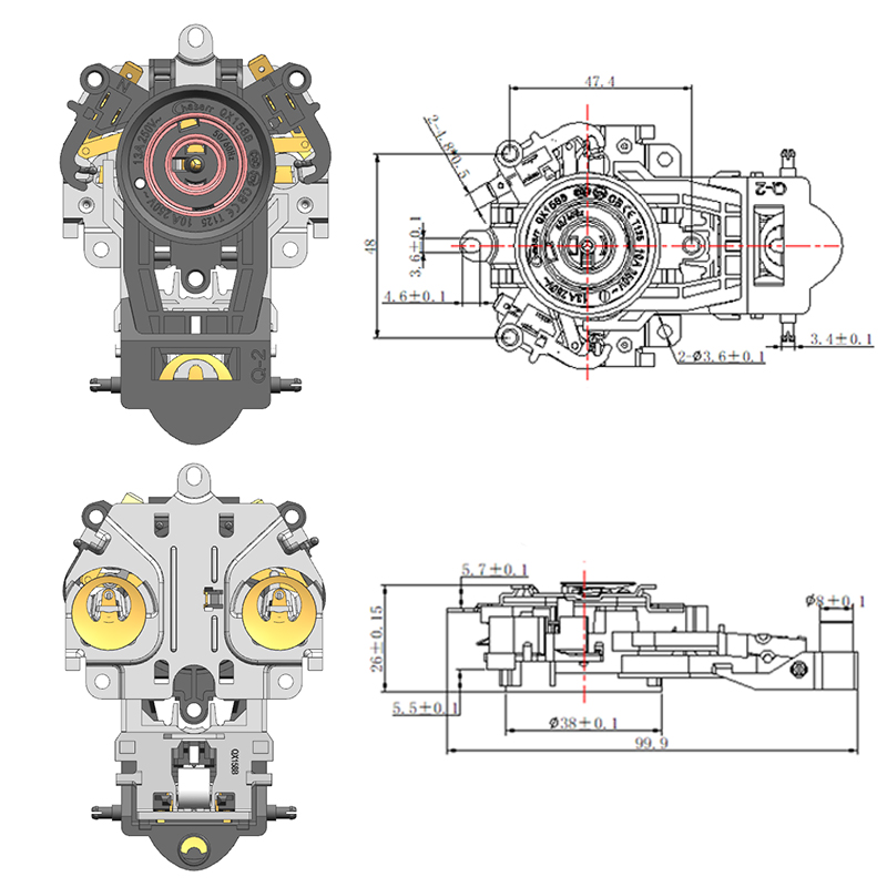
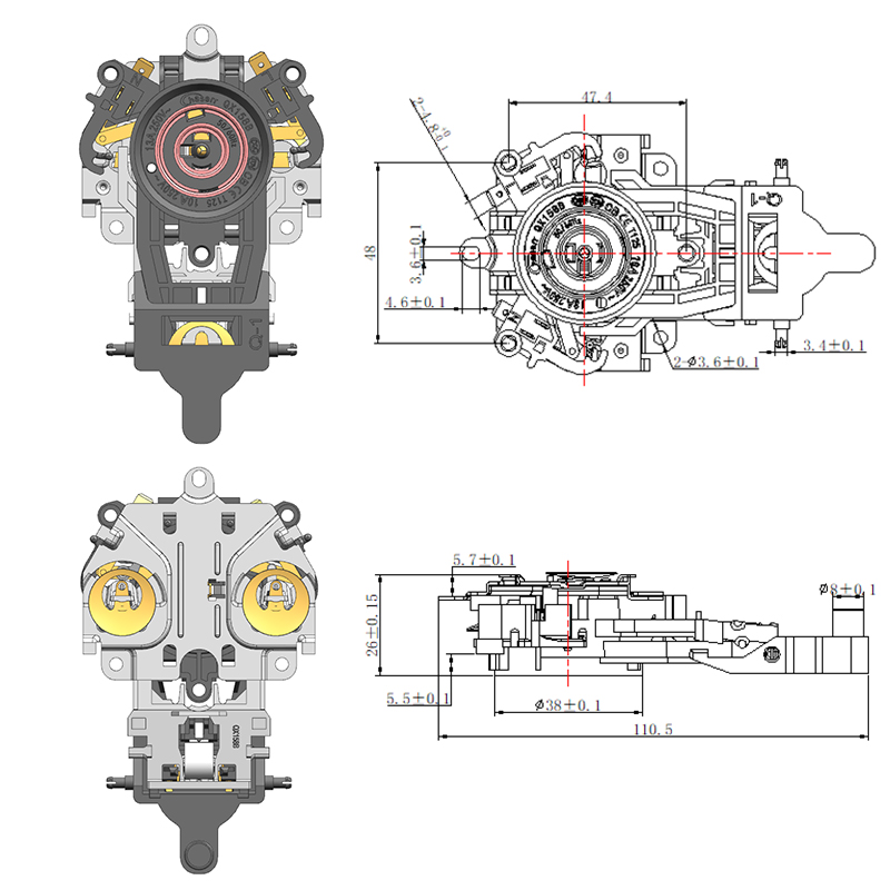

-
No. 2892, Ningkang East Road, Tiancheng Industrial Zone, Yueqing City, Zhejiang Province
-
 Email: Una@chaserr.cc
-
 Phone: +86-13075775533
- GET IN TOUCH

Electric Kettle Thermostat Coupler Manufacturer